Idea
As soon as the Raspberry Pi Compute Model 4 and IO board was announced, the idea rose in my head to mothball my former ZyXEL NSA325v2 (thanks for rendering me such a great service over the time 🙌) and build one NAS myself! 😏
Already with the ZyXEL device, I was able to install and boot a separate Debian Linux on an external USB drive and enhance the OEM firmware with some more flexible OS which I, in the end, used for making my first moves with OpenMediaVault (which started with major release 3). Liking this piece of software a lot, there was no other conclusion to use the most up to date version of OMV again, but with a lot more powerful hardware as a base.
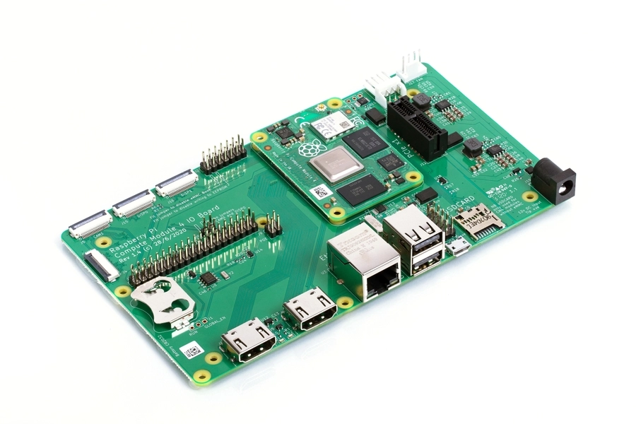
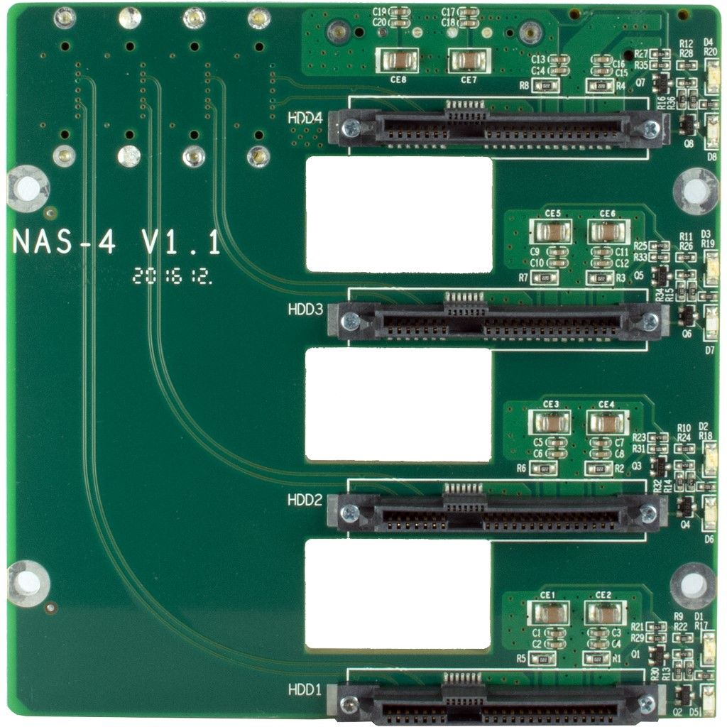
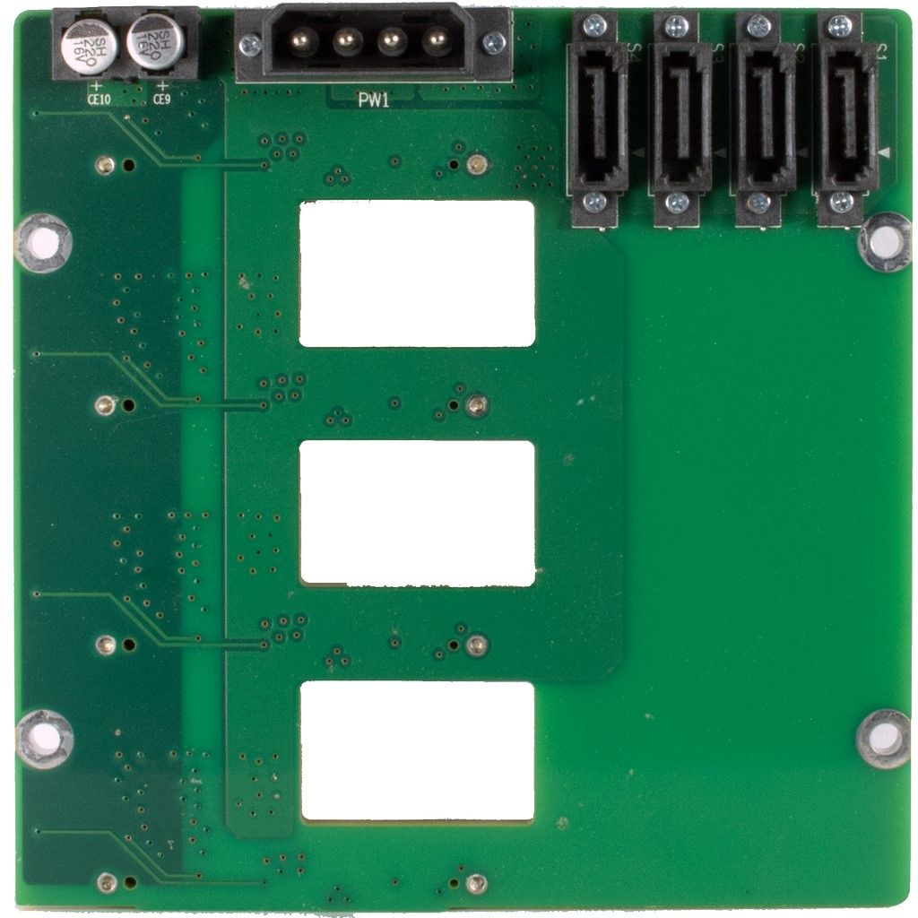
Adding a real PCIe x1 connector to the IO Board seemed like the perfect solution for bringing native S-ATA support to the Pi 4 (you can see in the 4th picture below). In general, the IO board offers a lot more connectivity as the regular RPi 4, without losing full GPIO capabilties and also being able to power it via two different power sockets. Only “problem” is it does not stick to any available form factor, but that can be taken care of.

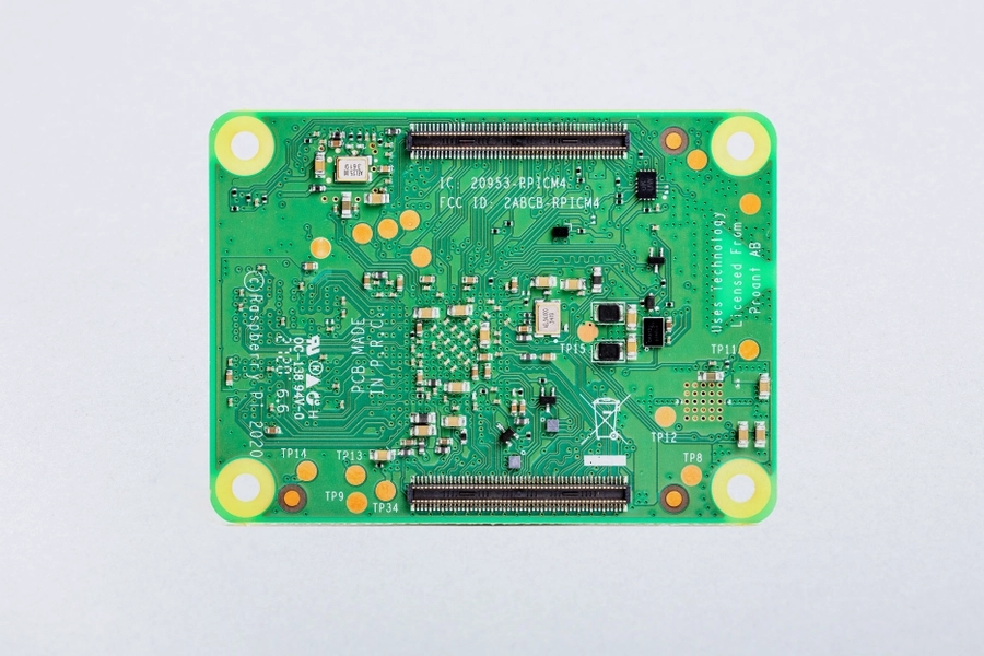

For the record, I ended up purchasing the CM4 unit with 32GB eMMC and 4GB 8GB RAM, plus the wireless chipset (you never know what it might be needed for in the future 😏).
Update 2022
After having run the NAS now for a few months, I ended up buying the 8 Gig RAM version of the CM4 since I often ran out of memory with a lot of services installed on the system, resulting in spontaneous reboots of the OS.
Which case?
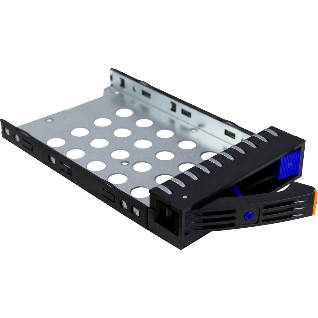
In order to find the right case for the NAS to fit in my living room, I looked at different cases to carry the CM4 Pi with the IO board, plus my former two Western Digital Red 8TB NAS hard drives (meanwhile RedPlus 10TB) I had set up as a RAID1.
It seemed very difficult to find a suitable case which is both quite good looking, but also well-built and small enough to be put in a living room environment. On top of that, noise is a non-underestimating factor when running the NAS 24/7 at a place were people spend more than 50% of their home time.
For this purpose, mostly mini-ITX cases were the only chance to consider. But also pricing was a reason for me, since if you built on top of a Raspberry Pi which itself is not that cost-intensive, why spend hundreds of Euros on a case?
So first, I tried the major brands and in the end had two candidates which made sense to me:
Out of these two, I ordered the first with a regular ATX power supply from be!quiet because it fitted more my personal preference. The case itself was of high quality, but failed rather quick due to too big dimensions (My girlfriend nearly ripped my head off after I told her I want to put this now next to the TV, were there was a spot left from the ZyXEL of less than half the size 😬)
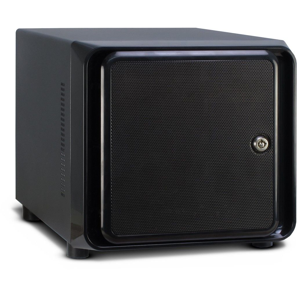
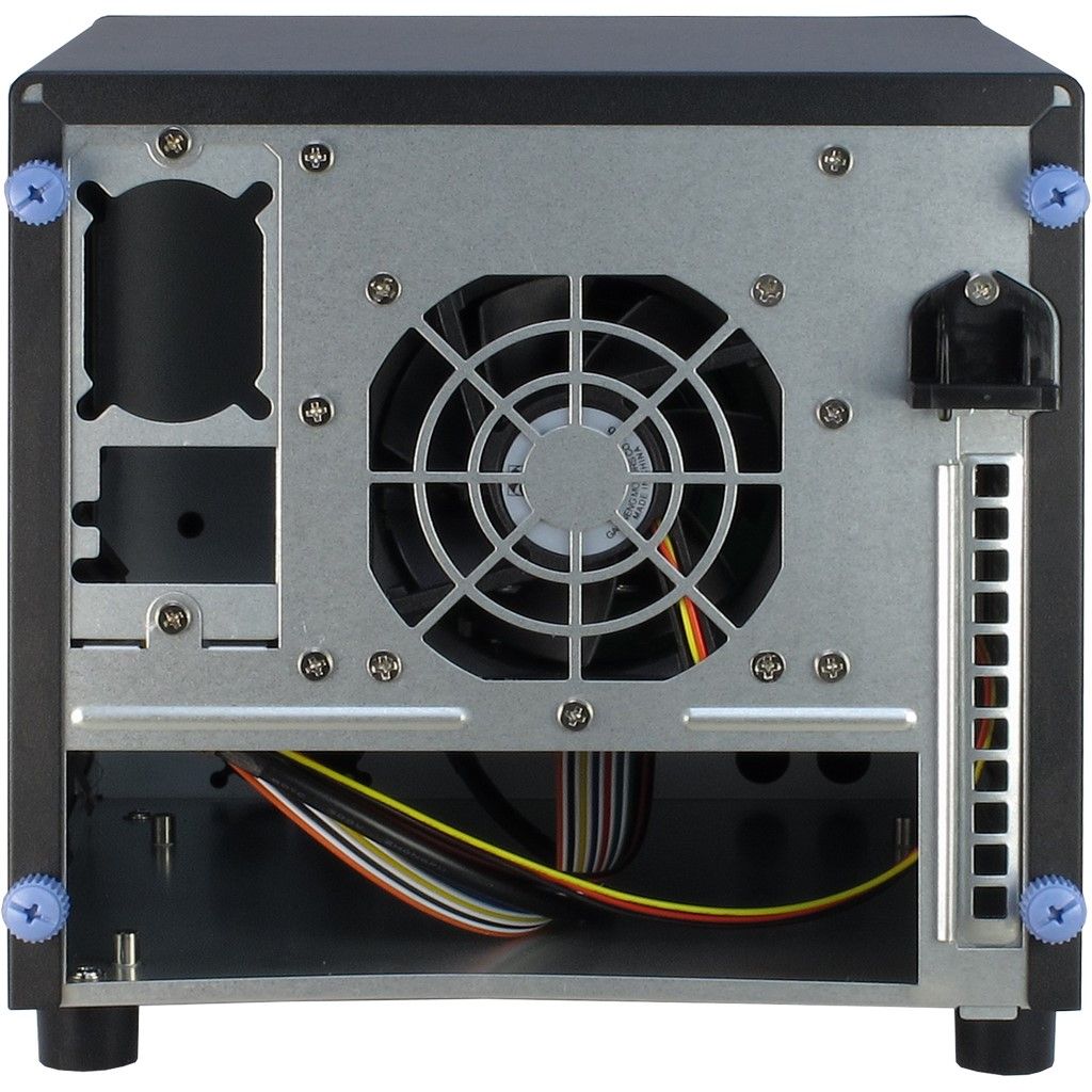
So with closer research, I found the perfect case from a small company in Germany called Inter-Tech.
These guys had two possible storage cases for mini-ITX in their portfolio:
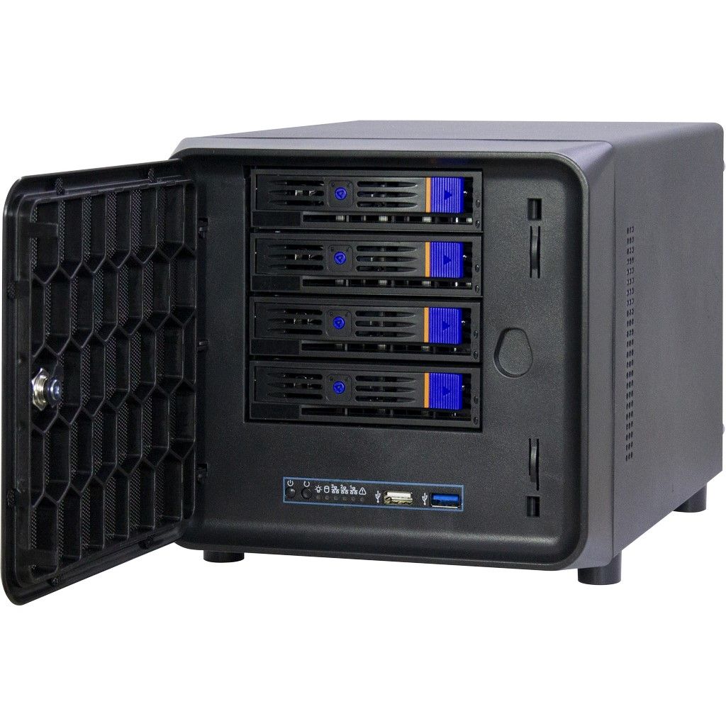
I first thought the 2-bay would be sufficient, since it should have carried the two 8TB hard drives only. But then I decided to go for the SC4100 to be more flexible on enhancements (later I remembered to still have a 4TB drive I was using before the RAID1 🧐)

Additional ingredients
So what was needed besides the Pi plus IO board, and the hard drives to succeed? 📋
Here you are
- Some old plexi glass to carry the board
- FlexATX power supply from FSP group
- 4-port S-ATA PCIe x1 Controller card, plus cables
PCIe x1 socket raiser cable- SSU-Tech PCIe x1 socket to x4 (2-port) raiser adapter card.
- Two yellow DeLock 82493 SATA cables (90° left ↔️ straight) for easier cable handling
- Two red DeLock 82603 SATA cables (90° left ↔️ straight) for easier cable handling
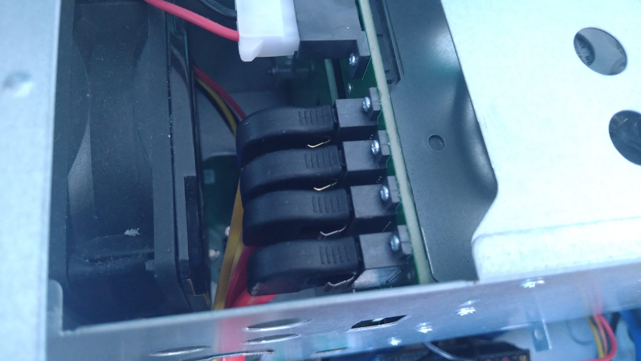
- Some NOISEBLOCKER low noise fans from BlackNoise, plus a cheap fan control
- Two pair of exchange rubber feet to get rid of vibration
- Patience and love for design 😉
Assembly
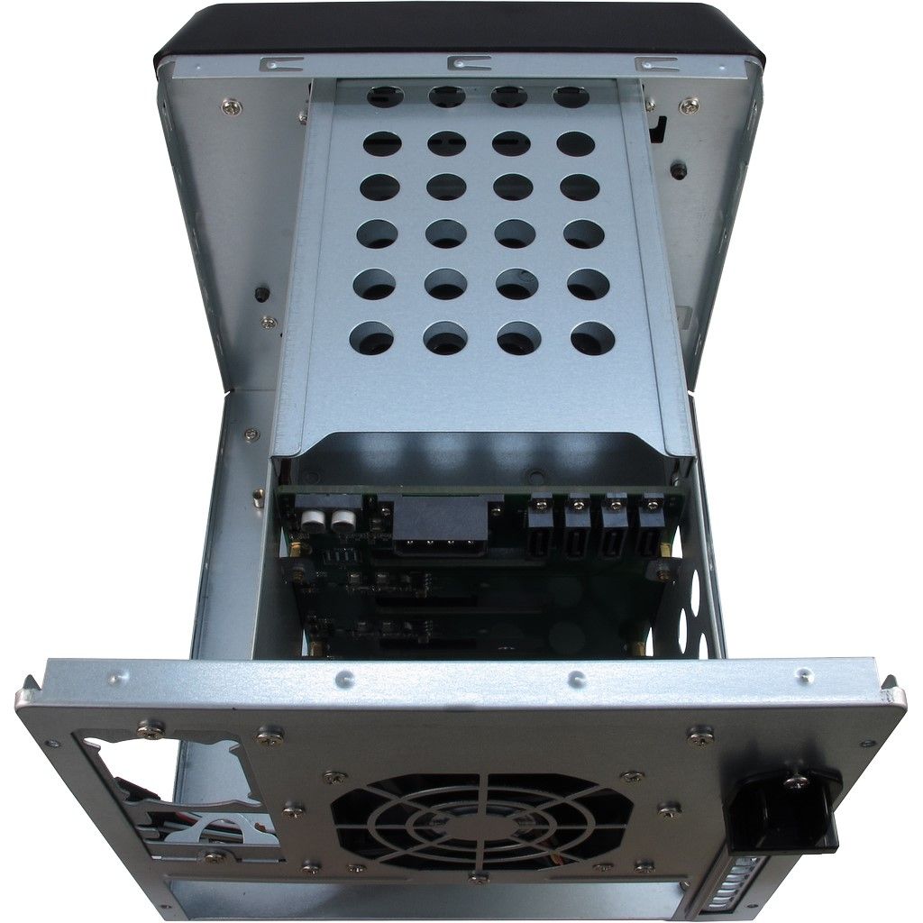
The most tricky part for the IO board is to fixate it in the chassis, due to the lack of mini-ITX support. To achieve this, I removed all the installed screw sockets and got in a different platform to put those sockets onto later.
I looked what I had available at home and found an old plexiglass plate remaining from other projects. I drilled some holes into the plate on the positions were the original screw sockets had been, and fixed the plate with some chassis screws. Now the foundation was given.
Most interesting was to place the board in such a way that all the IO board connectors are easily available. So I mounted the IO board with its predefined holes onto the former screw sockets from the chassis. Elevated like this, it was easier to mark the drill-out holes for the screw sockets on the plexiglass.
Since I did not want to use the regular 12V power socket on the IO board and instead use the floppy disk power connector coming from the PSU, the board was placed as much right as possible to cover the not needed jack.
For covering the back plate in the end I decided to rebuilt the original metal cover with a plastic one, due to the lack of proper tools to modify the metallic plate. To do so, a cheap plastic sign from a hardware store was purchased and cut, using the original as a template.


GPIO and Power board
Most difficult part was to handle the powering of the board. The absence of the ATX connector in combination with an ATX power supply might not seem very sophisticated, but using an mini-ITX case did not offer a lot of better options.
For that reason, a different solution was needed. In the beginning, I just connected pin 16 with pin 15 to generally power on the ATX PSU when plugged in. No chance for keeping it plugged in and controlling it with the buttons provided or powering off automatically when the RPi shut down.
Please see my dedicated post for what I did to solve this.
No responses yet